UML Diagrams
What is UML?
Unified Modeling Language also known as UML is a development modeling language in software engineering that is used to enhance the visualization of the design of any system and provide a standard way to do so. Visualization techniques are usually drawing multiple kinds of diagrams which represent the modeling criteria and basic architecture of anything. It is most widely used to model software solutions and business processes. UML developing standards are accepted by Object Management Group (OMG) and have been used widely to model software notations and artifacts. It is different than other programming language as it does not depend on any logic; it is a pictorial language which is used to create software blueprints.
UMLs are helpful in creating defined and concise descriptions of the whole software without wasting effort and time. These UML notations are understood worldwide and are a great way to define hierarchy of the components and subcomponents in a software product. The flow of information as well as the dependency of one object over another is easily denoted via different types of UMLs. These diagrams are extensively used in the documentation phases of the Software development life cycles (SDLC) to better illustrate the working of the final product. These UMLs are usually designed using specified UML designing tools for better presentation. As no great software can be made without the documentation was done properly, no documentation can be completed without the UMLs added to it. They serve as the basic asset of development in software engineering as they have the tendency to make everything much simpler and ready to go. There are many types of UMLs which are used in the industry but the most common ones will be discussed here in detail such as use case diagrams, class diagrams, architecture diagrams, entity relationship diagrams, sequence diagrams, state diagrams and package diagrams amongst others.
Goals of creating UML:
The UML comes in very handy in developing projects which follow object-oriented analysis and object oriented principles as it easily depicts the whole working of the softwares in one picture; as one picture describes a thousand words. The primary goal of UML is to consolidate the development of object development. It makes sure to provide a general standard language to be used by developers to visualize their softwares.
Concentrating on the modern world and its complexity; the UML has the ability to make things easier for the modeling industry and is a perfect tool to define a proper modeling mechanism.
Types:
There are various types of UMLs where each caters a specific type of problem and every UML has its own drawbacks and pros. Some of the most popular ones are discussed here as:
- Use-Case Diagram: These are the most popular and the basic diagrams which need to be built at the very beginning of the software development life cycle (SDLC) mainly in the first phase which is requirements gathering phase. Once the requirements are elicited, all the stakeholders can be identified immediately which can then be the key to making a Use Case Diagram. The Use case diagram is basically the representation of the actions of the users, their roles and how they will be interacting with the system.
The Diagram has a huge rectangle in which all the use cases are drawn, which is defined as the environment of the project model. At the very sides of this rectangle, the actors are drawn which have some impact on the project, in other words all the users are drawn here. No other systems can be actors in this case. Now, the relationships between these users are defined by the action that they will be performing with the project. Other than the direct interaction, two key terms are used which are extend and include. The term include is used where the next action is necessary and does not require a condition. Extend is used where a pre-condition is required in order for the next action to be done. Use case is a UML which can easily be used to depict all the functionality of the software project.
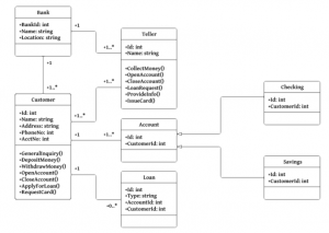
- Class Diagram: This is the most popular type of UML where the object oriented paradigm is used as it utilizes the characteristics of the Object oriented model (the classes, their objects and relationships between them). The class diagram can be easily used to describe the object oriented principles such as class composition, its attributes, inheritance, composition, abstraction and aggregation.
The class diagram starts with boxes where the heading is the class name. Public and private attributes and methods are denoted as + and -. The relationship and dependency between the classes are denoted by arrows. If two or more arrows move towards a single class, it denotes inheritance properties. If the goal is to portray composition, which is the strong relationship between classes, a filled diamond is drawn from the dependent class. In the same way, aggression is to be portrayed, an unfilled arrow is used similarly. The last thing is the simple linear line which depicts direct association between two classes.
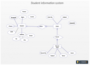
- Entity-Relationship Diagram: The entity relationship diagram, also known as ERD is used especially in the development of the databases as it can easily define the tables of the database and relate them with the primary-foreign key. The Entities are used as tables which are drawn in a small rectangle. And from it, lines are drawn towards ovals. These ovals are used to define the table attributes. These attributes can be of various types, such as multivariate, etc. The primary key and foreign keys in the attributes are underlined. The relationship between both the tables is defined by a diamond in which the type of the relationship is written.
The complex part of the system is that if two tables have a many to many relationship, a relation is broken into two one to one relationships to create one bridge table.
These were some of the most used UMLs in industry today and without these no proper documentation can be done. These UMLs are perfect for pictorial representations of the software products.